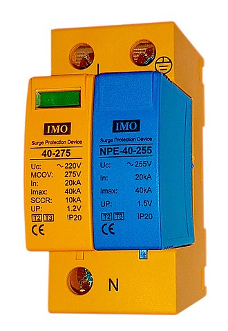
Electrical Testing
Battery Testing
There are many types of integrated battery testers, each one corresponding to a specific condition testing procedure, according to the type of battery being tested, such as the “421” test for lead-acid vehicle batteries. Their common principle is based on the empirical fact that after having applied a given current for a given number of seconds to the battery, the resulting voltage output is related to the battery’s overall condition, when compared to a healthy battery’s output.
Testing of Circuit Breaker
Testing of circuit breakers is more difficult as compared to other electrical equipment like transformer or machine because the short circuit current is very large. Testing of the transformer is mainly divided into two groups, type tests, and routine tests.
Type Tests of Circuit Breaker
Type tests are conducted for the purpose of proving the capabilities and confirming the rated characteristic of the circuit breaker. Such tests are conducted in the specially built testing laboratory. Type tests can be broadly classified as the mechanical performance test, thermal test, dielectric or insulating test, short circuit test for checking the making capacity, breaking capacity, short time rating current and operating duty.
Mechanical Test – It is mechanical ability type test involving the repeated opening and closing of the breaker. A circuit breaker must open and close at the correct speed and perform its designated duty and operation without mechanical failure.
Thermal Test – Thermal tests are carried out to check the thermal behavior of the circuit breakers. The breaker under test deal with the steady-state temperature rises due to the flow of its rated current through its pole in a rated condition. The temperature rise for rated current should not exceed 40° for current less than 800A normal current and 50° for normal value of current 800A and above.
Dielectric Test – These tests are performed to check power frequency and impulse voltage withstand capacity. Power frequency tests are kept on a new circuit breaker; the test voltage changes with a circuit breaker rated voltage.
The test voltage with a frequency between 15-100Hz is applied as follows. (1) between poles with circuit breaker closed (2) between pole and earth with circuit breaker open, and (3) across terminals with circuit breaker open.
In impulse tests impulse voltage of specified magnitude is applied to the breaker. For outdoor circuit dry and wet tests are conducted.
Short -Circuit Test – Circuit breakers are subjected to sudden short-circuits in short-circuit test laboratories, and oscillograms are taken to know the behavior of the circuit breakers at the time of switching in, during contact breaking and after the arc extinction.
The oscillograms are studied with particular reference to the making and breaking currents, both symmetrical and asymmetrical restriking voltages, and switchgear is sometimes tested at rated conditions.
Routine Tests of a Circuit Breaker
Routine tests are also performed as per recommendations of the standards of Indian Engineering Service and Indian Standards. These tests are performed on the manufacturers’ premises. Routine tests confirm the proper functioning of the circuit breaker. The routine tests confirm the proper functioning of the circuit breaker.
Power frequency voltage test being the same as mentioned under the heading of type tests, the millivolt drop test is performed to determine the voltage drop within the current path of the breaker mechanism. Operational test is performed on the breaker by simulating its tripping by artificially closing the contacts of the relays.
Current transformer (CT)
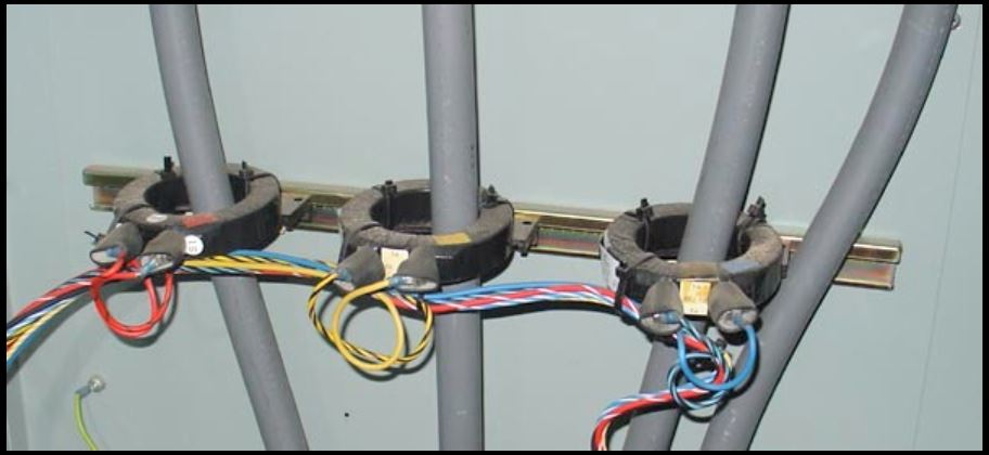
A current transformer (CT) is a type of transformer that is used to reduce or multiply an alternating current (AC). It produces a current in its secondary which is proportional to the current in its primary.
Current transformers, along with voltage or potential transformers, are instrument transformers. Instrument transformers scale the large values of voltage or current to small, standardized values that are easy to handle for measuring instruments and protective relays.
Current transformers are the current-sensing units of the power system and are used at generating stations, electrical substations, and in industrial and commercial electric power distribution.
Voltage Transformers (VT)
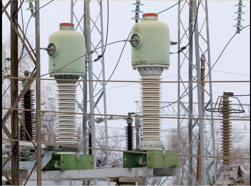
Voltage transformers (VT), also called potential transformers (PT), are a parallel-connected type of instrument transformer. They are designed to present a negligible load to the supply being measured and have an accurate voltage ratio and phase relationship to enable accurate secondary connected metering.
GIS Testing
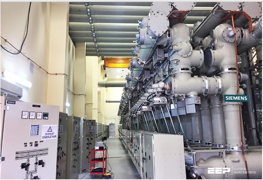
In an electric power system, switchgear is composed of electrical disconnect switches, fuses or circuit breakers used to control, protect and isolate electrical equipment. Switchgear is used both to de-energize equipment to allow work to be done and to clear faults downstream. This type of equipment is directly linked to the reliability of the electricity supply.
The earliest central power stations used simple open knife switches, mounted on insulating panels of marble or asbestos. Power levels and voltages rapidly escalated, making opening manually operated switches too dangerous for anything other than isolation of a de-energized circuit. Oil-filled switchgear equipment allows arc energy to be contained and safely controlled. a switchgear line-up would be a metal-enclosed structure with electrically operated switching elements using oil circuit breakers. Today, oil-filled equipment has largely been replaced by air-blast, vacuum, or SF6 equipment, allowing large currents and power levels to be safely controlled by automatic equipment.
High-voltage switchgear was invented at the end of the 19th century for operating motors and other electric machines.[1] The technology has been improved over time and can now be used with voltages up to 1,100 kV.[2]
Grounding resistance tester
A grounding resistance tester also called an earth tester is a soil resistance measuring instrument. It is used for sizing and projecting grounding grids.
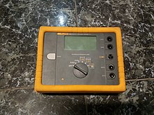
Digital Earth resistance tester
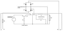
Analog Grounding resistance tester schematic
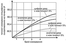
Graph of Comparison analog and digital grounding resistance testers
| Unit | operate at ambient temperatures | relative humidity | measuring ranges | error instrument |
| Grounding resistance tester M416 analog [11] | -25 ° C to +60 ° C | 95% |
1(0.1 Ohm – 10 Ohm); 2(0.5 Ohm – 50 Ohm); 3(2 ohms – 200 ohms); 4(10 Ohm – 1000 ohms) |
± (5 + (N/Rx-1)) |
| Grounding resistance tester UNI-T UT521 digital | -25 ° C to +60 ° C | 95% |
1(0 Ohm – 20 Ohm); 2(0 Ohm – 200 Ohm); 3(0 ohms – 2000 ohms); |
± (2 + (N/Rx-1)) |
| Grounding resistance tester Fluke 1621 digital | -25 ° C to +70 ° C | 98% |
1(0 Ohm – 20 Ohm); 2(0 Ohm – 200 Ohm); 3(0 ohms – 2000 ohms); |
± (2 + (N/Rx-1)) |
Transducer
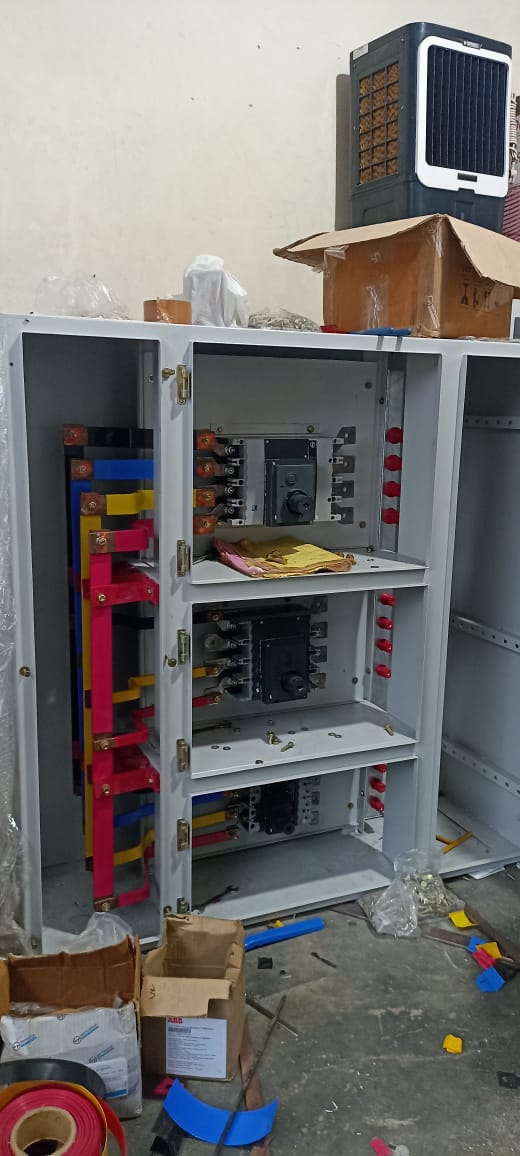
Electrical Panel Test
A suitable panel test requires having the right test devices to ensure a better and quicker work, which must have the proper flexibility to adapt to the different situations during the panel test; for 3 years,
NATIONAL ELECTRICAL POWER SERVICES is offering distinctive electrical panel test tools which are addressed to the user and the application, with a wide range of options to fit every need.
Power Transformer Testing
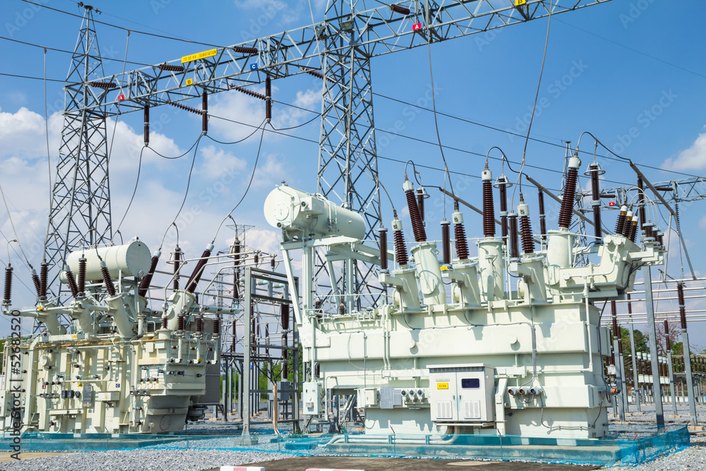
A transformer is a passive component that transfers electrical energy from one electrical circuit to another circuit, or multiple circuits. A varying current in any coil of the transformer produces a varying magnetic flux in the transformer’s core, which induces a varying electromotive force (EMF) across any other coils wound around the same core. Electrical energy can be transferred between separate coils without a metallic (conductive) connection between the two circuits. Faraday’s law of induction, describes the induced voltage effect in any coil due to a changing magnetic flux encircled by the coil.
Transformers are used to change AC voltage levels, such transformers being termed step-up or step-down type to increase or decrease voltage level, respectively. Transformers can also be used to provide galvanic isolation between circuits as well as to couple stages of signal-processing circuits. Since the invention of the first , transformers have become essential for the transmission, distribution, and utilization of alternating current electric power. A wide range of transformer designs is encountered in electronic and electric power applications. Transformers range in size from RF transformers less than a cubic centimeter in volume, to units weighing hundreds of tons used to interconnect the power grid.
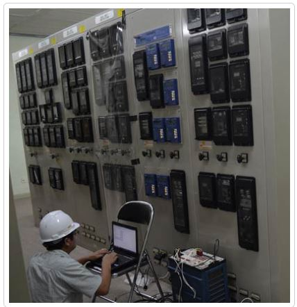
Protective Relay Testing
The testing and verification of protection devices and arrangements introduces a number of issues. This happens because the main function of protection devices is related to operation under fault conditions so these devices cannot be tested under normal operating conditions. This problem is worsened by the growing complexity of protection arrangements, application of protection relays with extensive software functionalities, and frequently used Ethernet peer-to-peer logic.
The testing and verification of relay protection devices can be divided into four groups: – Routine factory production tests – Type tests – Commissioning tests – Occasional maintenance tests TYPE TESTS Type tests are needed to prove that a protection relay meets the claimed specification and follows all relevant standards. Since the basic function of a protection relay is to correctly function under abnormal power conditions, it is crucial that the operation is evaluated under such conditions. Therefore, complex type tests simulating the working conditions are completed at the manufacturer’s facilities during equipment development and certification. The standards that cover majority of relay performance aspects are IEC 60255 and IEEE C37.90. Nevertheless, compliance may also include consideration of the demands of IEC 61000, 60068 and 60529, while products intended for installation in the EU also have to comply with the requirements of EU Directives. Since type testing of a digital or numerical protection relay includes software and hardware testing, the type testing procedure is very complex and more challenging than a static or electromechanical relay.
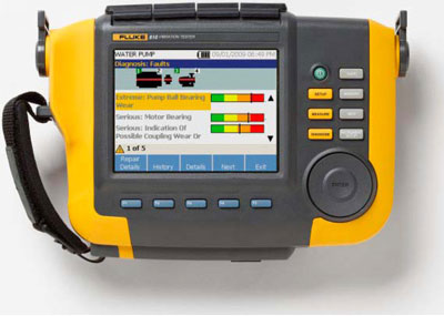
Rotating Machine Testing
Rotating Equipment is a term generally used in the oil and gas and process industries to describe mechanical components that use kinetic energy to move fluids, gases, and other process materials. These include, but are not limited to, engines, compressors, turbines, pumps, generators, blowers, and gearboxes. While rotating equipment plays an integral role in most operations, it is often managed separately from fixed equipment because it has different design, maintenance, and inspection requirements.


